For engineers and fabricators working on rack mount chassis, defense enclosures, mounting hardware, and telecom brackets, Z-bending eliminates welded joints and multi-part assemblies from designs that would otherwise require them. The result is a stronger, more consistent part produced in fewer operations.
This guide breaks down the three practical solutions for Z-shaped bending, when each approach fits, and the design variables that determine whether your flat blank comes out right the first time.
Key Takeaways
- Z-bending creates a stepped offset profile using two opposing bends from a single sheet
- Three solutions exist: two-stage sequential bending, single-stroke offset die bending, and CNC-automated multi-step bending
- Calculate bend allowance independently for each bend before developing the flat pattern
- Define step height, flange length, and springback compensation before production begins
- Material choice affects minimum bend radius and springback compensation requirements
What Is Z-Shaped Bending?
WILA defines offset bending (Z-bending) as two equal and opposite bends formed to create two parallel planes separated by a stepped web—the vertical distance between those planes is the step height, also called the Z-dimension.
Viewed from the side, the finished part traces a Z or S shape: a top flange, a diagonal web, and a bottom flange, all machined from a single flat sheet with no joins or welds.
How Z-Bending Differs from Related Operations
The three operations each produce a fundamentally different profile:
- V-bending forms a single angular bend over a V-die: one bend, one angle change
- U-bending creates a symmetric channel with two parallel legs pointing the same direction
- Z-bending is unique because its two bends oppose each other, producing an offset rather than a return profile
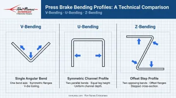
Because the bends work in opposite directions, tooling clearance between the first formed flange and the punch during the second bend becomes a direct constraint on minimum step height requirements and tooling selection.
The Three Solutions for Z-Shaped Bending
No single method covers all Z-bending scenarios. Material thickness, step height, production volume, and part geometry each influence which solution delivers the most accurate and cost-efficient result.
Solution 1: Two-Stage Sequential Bending with Standard Tooling
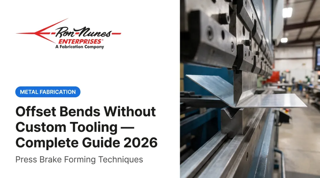
The sheet is bent first at one location using a standard V-die and punch on a press brake, repositioned by the operator or back gauge, then bent a second time in the opposite direction to complete the Z profile. No specialized tooling is required.
As described in The Fabricator's guide to forming offsets, the conventional two-hit method adds a second ram cycle and may require turning the part between bends—introducing the risk of accumulated positioning error if back gauge repositioning isn't carefully controlled.
Modern CNC press brakes address this directly. The X-axis controls bend depth, the R-axis adjusts finger height between bends, and Z1/Z2 axes reposition fingers laterally—allowing both bends to be sequenced without setting the part down.
Best suited for:
- Low-to-medium production volumes and prototype runs
- Parts with larger step heights where offset die tooling isn't available
- Shops needing maximum tooling flexibility across different Z-heights
Watch out for: Front-gauging from a formed feature (rather than an outside edge) is preferable when a critical dimension exists between the two flanges—gauging from the outside edge can transfer blank-size variation directly into your flange-to-flange measurement.
Solution 2: Single-Stroke Offset Die Bending
A dedicated offset punch and die set—engineered with a stepped geometry that mirrors the target Z profile—forms both bends simultaneously in a single downward press stroke. Both bends happen at once, eliminating the second ram cycle and the repositioning step entirely.
Key specifications for standard offset tooling:
| Parameter | Published Value |
|---|---|
| Maximum Z-dimension (WILA standard) | 15 mm |
| Corresponding V-opening | ~20 mm |
| Maximum material thickness | Up to 3 mm (subject to tool load) |
| Mate insert configurations | 26 sizes; 90°, 140°, 150°, 160° included angles |
One important caveat: the 15 mm limit is a manufacturer-specific standard-tool maximum for WILA's current catalog. It is not a universal industry standard. Wilson Tool also documents a horizontal-offset configuration for offsets of approximately one material thickness, covering the opposite extreme. Your achievable range depends on the specific tooling set in use.
Best suited for:
- High-volume production runs where cycle time and consistency are priorities
- Recurring step heights that fit a qualified tool set
- Applications where minimal part handling matters
Not ideal for: Prototyping or designs with variable step heights—each tooling set targets a fixed Z-geometry, so switching step heights requires a different tool.
One additional note: Offset tooling generates outward side thrust during the stroke. Uncontrolled side thrust can damage tooling or the workpiece, so proper tool clamping and alignment are required to prevent tool damage or part distortion.
Solution 3: CNC-Automated Multi-Step Bending with Programmable Back Gauge
Where Solutions 1 and 2 hit limits—positioning error risk or fixed tooling geometry—a CNC press brake with a programmable back gauge fills the gap. The back gauge moves to the exact location for each bend automatically. The bend sequence is programmed into the machine, and the press repeats the operation with consistent accuracy across the entire batch.
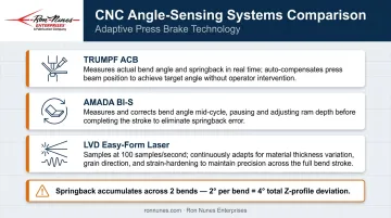
Several manufacturers have pushed this further with real-time angle sensing:
- TRUMPF ACB measures actual angle and springback, controlling the press beam to compensate automatically
- AMADA BI-S measures and corrects bend angle during the bending cycle itself
- LVD Easy-Form Laser samples angle data at 100 times per second, adapting punch position for thickness, grain, and strain-hardening variation in real time
This matters for Z-bending specifically because springback accumulates across two bends. A material that springs back 2° per bend produces a 4° total deviation in the finished Z-profile—a problem that angle-sensing systems catch and correct before the part is unloaded.
Best suited for:
- Medium-to-high volume runs requiring tight dimensional tolerances across both bends
- Complex parts combining Z-bends with holes, flanges, and cutouts
- Springback-prone materials: stainless steel, 7075 aluminum, high-strength alloys
Upfront programming takes time, but once a program is qualified, scrap rates drop and operator involvement between cycles is minimal—making it the most repeatable option for production runs where both bends carry tight tolerances.
Key Design Considerations for Z-Bending
Bend Allowance Across Two Bends
Because Z-bending involves two bends, bend allowance must be calculated independently for each and both values subtracted from the flat blank length. The standard formula:
BA = A × (π/180) × (R + K × T)
Where:
- A = bend angle in degrees
- R = inside radius
- K = K-factor (neutral axis position; general range 0.33–0.50, with 0.4468 commonly used as an average)
- T = material thickness
For a Z-bend with two 90° bends, you're running this calculation twice—once per bend—and summing the results. Skipping this step is the single most common cause of finished parts that come out shorter or longer than designed.
Minimum Step Height
The step height must be large enough to prevent the punch from colliding with the already-formed flange during the second bend. As a working design rule, step height should be at least 2.5× the material thickness for most ductile metals, though exact minimums depend on die slot width, punch geometry, and the specific bending method. Stainless steel typically requires slightly larger minimums.
Confirm minimum step height against your specific tooling before finalizing the design.
Minimum Flange Length
Both flanges must be long enough for the punch and die to engage the material properly. Published guidance from The Fabricator puts minimum flange length at approximately 77% of V-opening for standard V-dies. Very short flanges may require custom tooling or secondary operations to achieve acceptable bend quality.
Springback Compensation
Sheet metal partially recovers its original shape after the bending force is released. In Z-bending, springback accumulates across both bends, making it more consequential than in single-bend operations.
Two main compensation approaches:
- Overbending — bend past the target angle so the part springs back to the correct angle on release
- Bottom bending / coining — apply higher tonnage to set the bend more permanently through greater plastic deformation
High-strength alloys like 7075 aluminum and 316L stainless steel require more aggressive compensation. Aalco's stainless fabrication literature explicitly notes that stainless steels spring back more than mild steel. Overbend angles dialed in on a mild steel job will not transfer directly to stainless — recalculate for each material.
Grain Direction
Bending perpendicular to the material's rolling grain direction reduces cracking risk, especially at tight radii. A bend line parallel to the grain is weaker and more prone to cracking than a cross-grain bend line. For aluminum alloys in harder tempers, where ductility is limited, grain orientation needs to be set at the design stage — not resolved during fabrication.
Where Z-Bending Is Applied
Z-bends show up across a wide range of industrial applications:
- Equipment brackets and mounting tabs that offset one assembly plane from another
- Rack mount chassis panels and internal frames, where stepped flanges allow components to nest or stack without spacers
- **Enclosure lips and stepped flanges** for snap assembly without additional hardware
- Structural supports and transition pieces in HVAC, automotive, and defense hardware
- Stepped stiffeners in telecom and electronics enclosures
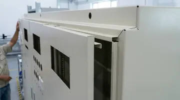
Z-bends are a design-stage decision. They get planned into the flat pattern during product development and executed during primary fabrication. Trying to retrofit a Z-bend into a design that wasn't laid out for one creates avoidable tooling and tolerance problems.
Ron Nunes Enterprises has been forming sheet metal in Livermore, California since 1969. Their press brake work covers Z-bends across rack mount chassis, custom brackets, and structural hardware for defense, telecom, and electronics programs — from early prototypes through full production runs.
Common Mistakes in Z-Bending and How to Avoid Them
1. Missing bend allowance on one of the two bends
Flat pattern development for Z-bends requires two separate BA calculations. Designers who apply one deduction and assume symmetry end up with a blank that's dimensionally wrong after forming.
Calculate each bend independently. The Fabricator recommends establishing the flat with a test bend rather than relying solely on textbook calculations, since material trapped between closely spaced bends doesn't elongate the way independent bends do.
2. Step height too small for available tooling
A step height that looks fine on a drawing can cause the punch to collide with the first-formed flange on the second pass. Check your minimum step height against the specific tooling being used—not just a rule of thumb—before the design is released.
3. Underestimating springback across materials and gauges
Springback varies with material thickness, strength, grain direction, and work hardening. An overbend setting dialed in for 5052-H32 aluminum will not transfer cleanly to 304 stainless of the same gauge. Run springback test bends on sample material at the start of any new job and adjust the bend program accordingly.
Catching these issues before forming begins saves scrap, rework time, and tooling wear—particularly on close-tolerance Z-bends where compounding errors are difficult to correct after the fact.
Frequently Asked Questions
What is the bend allowance for sheet metal?
Bend allowance is the arc length consumed in the bend zone, calculated as BA = A × (π/180) × (R + K × T). Subtract this value from each flat blank dimension to get the correct pre-bend length per flanged segment.
What are the different types of bending in sheet metal?
The main types are air bending, bottom bending (bottoming), coining, V-bending, U-bending, Z-bending (offset bending), and roll bending. Each differs in tooling contact, applied tonnage, achievable accuracy, and springback behavior.
What is the minimum step height for a Z-bend?
Step height should be at least 2.5× material thickness to avoid tooling interference. Exact minimums vary by die slot width, material type, and bending method. Consult material-specific tooling reference tables for your setup.
What is the difference between Z-bending and offset bending?
They are the same process. Both terms describe a two-bend operation that creates a stepped Z-shaped profile, and they are used interchangeably in press brake tooling catalogs and fabrication literature.
Can a Z-bend be formed in a single press stroke?
Yes. Specialized offset dies are designed to form both bends simultaneously in one downward stroke, making single-stroke Z-bending viable for fixed step heights and thin-to-medium material thicknesses.
What materials are best suited for Z-bending?
Mild steel and aluminum alloys with good ductility—such as 5052-H32—are the most straightforward materials for Z-bending. Stainless steel works but requires larger bend radii and more springback compensation. High-strength alloys like 7075 aluminum or 316L stainless should be prototyped and tested before committing to production parameters.