Introduction
In precision manufacturing, a failed weld doesn't just mean rework — it can mean a scrapped aerospace assembly, a contaminated medical device housing, or a rejected defense enclosure. When dimensional accuracy and material integrity are both on the line, process selection matters as much as execution.
TIG welding (GTAW — Gas Tungsten Arc Welding) is the process engineers reach for when those stakes are highest. It's widely specified across semiconductor equipment frames, structural defense assemblies, and medical housings — but the process variables that determine weld quality are frequently underestimated at the design and procurement stage.
This guide explains how TIG welding actually works — what happens at each stage of the process, what variables control weld quality, and the best practices that separate consistent precision output from costly rework.
Key Takeaways
- TIG welding uses a non-consumable tungsten electrode to generate an arc; filler rod is fed separately by hand or mechanized feeder
- Argon shielding gas protects the weld zone from oxidation throughout the entire weld cycle
- The welder simultaneously manages amperage, arc length, torch angle, and filler feed, making TIG the most skill-intensive common arc process
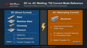
- DC current is used for steel and stainless; AC is required for aluminum to break the oxide layer
- TIG produces spatter-free, narrow-bead welds with minimal heat-affected zones, making it the preferred process for thin metals and exotic alloys
What Is TIG Welding?
TIG stands for Tungsten Inert Gas. Its formal AWS designation is GTAW (Gas Tungsten Arc Welding) — a constant-current arc process using a non-consumable tungsten electrode and inert shielding gas. ISO 4063:2023 classifies it as process reference 141 (GTAW with solid filler material).
Why TIG Exists
The process traces back to Russell Meredith's 1941 patent for "Heliarc" welding, developed specifically to join magnesium and aluminum alloys that older arc processes couldn't weld reliably without contamination. That original purpose still defines TIG's niche: aerospace frames, medical implants, semiconductor enclosures, and any application where a contaminated or inconsistent weld is a rejection, not a rework.
What Makes TIG Different from MIG
This distinction matters operationally:
- MIG (GMAW): Wire electrode feeds continuously through the gun and melts into the weld. Semi-automatic. Faster, less operator-intensive.
- TIG (GTAW): The tungsten electrode does not melt. It generates the arc. Filler metal is introduced separately — either by hand dipping a rod into the pool or via a mechanized wire feeder. Fully manual or automated, never semi-automatic.
Because heat input, shielding, and filler addition are all controlled independently, TIG operators can dial in each variable separately — which also means the process demands more skill and attention than MIG.
DC vs. AC Current Modes
The current mode is determined by the base material — get it wrong and you'll either contaminate the weld or fail to penetrate the oxide layer:
- DC (Direct Current): Used for steel, stainless steel, chromoly, titanium, and most metals. Produces a stable arc with focused penetration.
- AC (Alternating Current): Required for aluminum. The electrode-positive portion of the AC cycle provides cleaning action that breaks the aluminum oxide layer; the electrode-negative portion delivers penetration. According to Miller Welding, AC balance control lets operators adjust the proportion of cleaning to penetration — too much cleaning and the electrode balls up; too little and the oxide layer contaminates the pool.
How Does TIG Welding Work?
TIG welding runs through a defined sequence: arc initiation → pool formation → shielding gas protection → filler addition → weld termination. Each stage must be controlled to get consistent results.
Initiation
Modern TIG machines use high-frequency (HF) arc start — a high-voltage, low-current spark jumps the gap between the tungsten and the workpiece without contact. This prevents tungsten contamination at startup. Lift-arc and scratch-start are simpler alternatives, but both increase contamination risk and are generally avoided on precision work.
Before the arc ignites, shielding gas flows for a brief pre-flow period to purge oxygen from the torch hose and weld zone. Skipping or shortening this step is a documented cause of porosity and oxidation in the early part of the bead.
Core Operation
The tungsten electrode (melting point approximately 3,422°C / 6,192°F per NIH PubChem data) carries electrical current that arcs as plasma to the base metal. The arc transfers heat energy to the workpiece, forming a molten weld pool; the electrode itself stays solid.
Filler metal introduction:
- The welder (or mechanized feeder) dips the filler rod into the leading edge of the weld pool
- The pool melts the filler, not the arc directly
- Dip rate, arc length, and travel speed must be coordinated continuously
The three variables that interact constantly:
| Variable | Effect | Compensation Required |
|---|---|---|
| Amperage | Controls heat input and penetration | Adjust travel speed to match |
| Travel speed | Controls bead width and penetration depth | Slow down = more heat input |
| Torch angle | Affects pool visibility and gas coverage | Typically 10–20° from vertical, tilted in direction of travel |
Varying any one of these requires compensating adjustments in the others — which is why real-time control over amperage becomes so critical during the weld.
Regulation and Control
Most TIG setups use a foot pedal or thumb control for real-time amperage modulation. The welder increases heat to penetrate thicker sections, then reduces it when approaching thin edges or the end of the weld to prevent burn-through. This live adjustment is one of TIG's key advantages over fixed-parameter processes.
Shielding gas management is equally critical. Per Lincoln Electric equipment guidelines, argon flow rates vary by electrode size and material — starting points range from 5–10 CFH for 1/16" electrodes on steel up to 15–23 CFH for 1/8" electrodes on steel, with aluminum typically running slightly higher.
Miller Welding notes that excessive flow creates turbulence that pulls ambient air into the shield zone, defeating its purpose. Gas lens accessories improve laminar flow and are standard practice for precision work.
Output and Termination
A correctly executed TIG weld produces a narrow, consistent bead with full fusion, minimal heat-affected zone, no spatter, and a surface that typically requires no post-weld grinding.
Weld termination requires care:
- Never stop abruptly — this causes crater cracks and exposes the still-hot pool to air
- Use the foot pedal to gradually ramp down current, or use the machine's crater-fill function
- Hold the torch in position through the full post-flow cycle — Miller's guideline is post-flow seconds equal to welding amperage divided by 10, with a minimum of 8 seconds
- Maintain post-flow to protect both the cooling weld and the tungsten tip from oxidation
TIG Welding Equipment and Setup
Key System Components
A functional TIG welding system requires:
- Power source — constant-current output (CC), not constant-voltage
- TIG torch — air-cooled for lower amperages (typically under 200–250A); water-cooled for sustained high-amperage work or where torch size matters
- Tungsten electrode — sized and prepared to match current type and base material
- Shielding gas supply — cylinder, regulator, and flow meter
- Amperage control — foot pedal or thumb control for real-time modulation
Tungsten Electrode Selection
Electrodes are classified per AWS A5.12M/A5.12:2024 and color-coded by alloy:
| Color | Classification | Application |
|---|---|---|
| Green | EWP (Pure tungsten) | Traditional AC aluminum choice |
| Red | EWTh-2 (2% Thoriated) | DC steel and stainless |
| Gold | EWLa-1.5 (1.5% Lanthanated) | DC and AC applications |
| Blue | EWLa-2 (2% Lanthanated) | All-purpose AC/DC per Miller |

Tip geometry matters:
- Pointed tip for DC: produces a focused, stable arc suited to steel and stainless
- Balled tip for AC: forms naturally on pure tungsten when welding aluminum
On modern inverter-based machines, lanthanated tungsten with a pointed or truncated tip works well for AC aluminum work. The "always ball for AC" rule applies to conventional transformer-based machines, not current inverter technology.
Surface Preparation
TIG is unforgiving of contamination. Before welding:
- Remove mill scale, oil, paint, rust, and oxidation
- Use dedicated stainless wire brushes for aluminum — Hobart and AWS both specify brushes dedicated to aluminum to avoid cross-contamination
- Never share brushes between carbon steel and aluminum or stainless work
- Solvent clean (acetone or equivalent) before brushing, especially on aluminum
Best Practices for Precision TIG Welding
Body Position and Physical Setup
Before striking the arc, establish stable body position. Key setup requirements before starting any weld:
- Rest the torch hand on a firm surface or prop for stability
- Position your stance so the torch travels the full weld length without mid-weld repositioning
- Lock in electrode-to-work distance within a narrow range — Miller recommends 1/16 to 1/8 inch as a practical starting point
Arc length consistency is only achievable when body mechanics are set before the arc starts.
Torch Angle and Direction of Travel
ESAB's TIG process guide recommends angling the torch approximately 10–15 degrees in the direction of travel. This orientation improves shielding gas coverage over the weld pool and gives the welder clear sightlines to the pool leading edge.
Power Management
Set amperage conservatively and use the foot pedal to add heat as needed — not the other way around. This approach lets the welder:
- Respond to changes in base metal thickness mid-joint
- Compensate for fit-up gaps that widen or narrow
- Manage heat accumulation on longer welds without burn-through
Weld Termination
Use the foot pedal to gradually reduce current at the weld end. Don't release abruptly. Then:
- Maintain torch position through the complete post-flow cycle
- Let the shielding gas protect the crater as it cools
- Inspect the crater — it should be filled, not concave or cracked
Consumable Management in Multi-Material Shops
When switching between base materials, particularly from carbon steel to stainless or aluminum, replace all contact surfaces:
- Replace the tungsten electrode
- Replace the gas lens and collet body
- Use material-dedicated filler rods stored separately
- Use dedicated wire brushes per material type
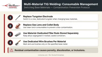
Residual contamination from previous materials shows up as porosity, discoloration, or inclusions — defects that mean rework or scrap on aluminum and stainless welds.
Where TIG Welding Is Used
TIG fits specific positions in manufacturing and fabrication workflows:
- Root pass welding — the first, most critical pass in multi-pass pipe and pressure vessel welds. A 2024 ASME Journal of Pressure Vessel Technology article confirms GTAW as best practice for root and hot passes in piping and pressure-vessel applications.
- Thin-gauge sheet fabrication — material under 4mm where heat control and distortion prevention are priorities
- Precision assemblies — where dimensional accuracy, weld appearance, and surface condition are specified
Where TIG Performs Best
- Controlled shop environments with stable gas coverage (wind and drafts disturb shielding gas and require windshields or enclosures as controls)
- Clean base materials and skilled operators
- Applications where slower welding speed is acceptable in exchange for superior weld quality
- NOT cost-effective on thick material where MIG or submerged arc can deposit filler metal far faster
Industries That Specify TIG
Aerospace, defense, semiconductor equipment manufacturing, medical devices, nuclear systems, and telecommunications infrastructure all specify TIG where weld integrity, cleanliness, and traceability are requirements.
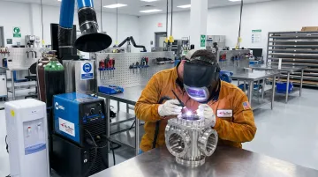
Ron Nunes Enterprises, a Livermore, California fabrication shop serving semiconductor, defense, nuclear research, and medical customers since 1969, treats TIG capability as foundational to its operation. Five Miller TIG welders staffed by Class A/XX certified welders run alongside MIG, spot, and stud welding stations — so process selection follows what each application actually requires.
Frequently Asked Questions
What exactly is TIG welding?
TIG (Tungsten Inert Gas) welding — formally designated GTAW (Gas Tungsten Arc Welding) — uses a non-consumable tungsten electrode to generate an arc that melts the base metal. A separate filler rod is added by hand or mechanized feeder, while inert shielding gas protects the weld zone from atmospheric contamination.
What is TIG welding best for?
TIG is best suited for thin-gauge metals, stainless steel, aluminum, titanium, and nickel alloys where high visual quality, zero spatter, full penetration, and tight dimensional control are required. Aerospace, medical device, defense, and precision fabrication shops rely on it as their standard process.
Which is better: MIG welding or TIG welding?
Neither is universally better — they solve different problems. MIG is faster and better suited for thicker materials and higher-volume production. TIG is superior for precision work, thin materials, exotic alloys, and applications where weld quality and appearance are critical. The right choice depends on material, thickness, and quality requirements.
What shielding gas is used in TIG welding?
Argon is the most common TIG shielding gas due to its stable arc characteristics. Helium or argon-helium mixtures are used where deeper penetration or faster travel speed is needed — particularly on thick aluminum or copper alloys. Linde's TIG gas selection data describes argon as providing strong puddle control and helium as delivering the deepest penetration and greatest welding speeds.
What materials can be TIG welded?
TIG is compatible with stainless steel, carbon steel, aluminum, nickel alloys, copper, titanium, magnesium, brass, bronze, and chromoly. It's particularly useful where contamination or distortion are primary concerns.
Is TIG welding harder than MIG welding?
Yes, and by a wide margin. TIG requires the operator to simultaneously control torch movement, feed filler rod by hand, and modulate amperage with a foot pedal — all while maintaining a precise arc length. AWS notes that GTAW has a steeper learning curve than semi-automatic GMAW, requiring substantially more training time to produce consistent results.