Many designers assume a revolve feature and a flatten command will do the job. It won't, at least not on its own. Getting a curved sheet metal part to unroll cleanly requires a defined seam, the right sheet metal command, and a few parameter checks most tutorials skip.
This guide walks through the exact steps to model and flatten cylindrical sheet metal faces, the parameters that determine flat pattern accuracy, the mistakes that trip up even experienced users, and what happens once the file leaves CAD and heads to a fabrication shop.
Key Takeaways
- Cylindrical parts need a defined seam and Insert Bends, not a solid revolve
- Convert to Sheet Metal needs a fixed reference face; cylinders often need Insert Bends
- Curved-face cuts use a straight cut-extrude or the Wrap feature for embossed details
- Weld-ready flat patterns depend on bend radius, K-factor, and seam gap control
How to Create Sheet Metal Parts with Cylindrical Faces in SolidWorks
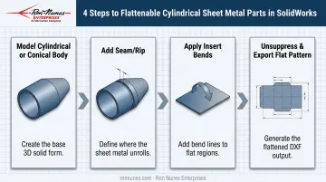
The general workflow follows four steps: build the cylindrical or conical solid, define a seam (called a rip in SolidWorks), apply Insert Bends, then unsuppress the flat pattern. Skipping the seam step is the single most common reason a curved part refuses to flatten.
Step 1: Model the Cylindrical or Conical Body
Start with a revolve for a full cylinder or cone, or use a Base Flange built from a curved profile. Keep wall thickness matched to your intended sheet metal gauge from the start.
If you're working with a pure cylinder, confirm the part has no flat, planar face yet. That detail matters later, since it determines whether Convert to Sheet Metal or Insert Bends is the right tool for your geometry.
Step 2: Add a Parting Line or Seam
Every hollow cylindrical or conical body needs a rip before it can flatten. According to SolidWorks Help on creating rips in cylindrical or conical models, you define this by selecting an edge on the curved face along with a reference point.
Two common approaches:
- Cut-Extrude a thin line (roughly 0.01 inch) through the body to create the seam that becomes the flat pattern's cut edge
- Reduce a revolve angle slightly (348° instead of 360°, for example) to leave a natural gap instead of cutting one in afterward
Some practitioners angle this seam line rather than cutting it square, aiming to keep the resulting edge closer to perpendicular once the part unrolls. It's worth testing on your specific geometry, but don't treat it as a guaranteed fix.
SolidWorks' documented rip workflow is built around straight edges, so validate your flat pattern visually after applying it either way.
Step 3: Apply Insert Bends
Select Insert Bends from the Sheet Metal toolbar. Per SolidWorks Help on Insert Bends, when your part has no planar face, you can select a linear edge as the fixed entity instead. This is the command Convert to Sheet Metal typically can't handle on curved-only geometry.
Set your bend radius and K-factor values to match the actual material and thickness you're specifying, not defaults. These numbers drive every downstream calculation.
Step 4: Unsuppress and Export the Flat Pattern
Find the auto-generated Flat-Pattern feature in the FeatureManager tree and unsuppress it. This reveals the unrolled geometry.
Before exporting, check that cut edges remain close to perpendicular relative to the flattened face. Then right-click Flat-Pattern and export to DXF or DWG for manufacturing. Skipping the unsuppress step is a surprisingly common error, one we cover in the mistakes section below.
Alternative Methods for Modeling Curved and Cylindrical Faces
The "best" method depends on whether you're working with a simple cylinder, a curved face that needs cutouts, or an imported solid body that already exists.
Convert to Sheet Metal (for Imported or Solid Bodies)
Convert to Sheet Metal asks you to select one fixed face along with thickness, bend radius, and rip settings. This tool works well on imported solid or surface bodies. For a pure cylinder with no obvious flat reference, you may need to add a temporary flat section or switch to Insert Bends, which handles linear-edge references more directly.
Wrap Feature (for Cuts on Curved Surfaces)
Wrap projects sketch geometry onto a face using three options:
- Emboss raises the geometry above the surface
- Deboss indents the geometry into the surface
- Scribe imprints just the outline
To cut a shape into a curved wall, sketch the slot or profile on a flat reference plane, then apply Wrap with Deboss selected. This is a detailing tool, not a sheet metal conversion command. It changes the face's appearance but doesn't calculate a flat pattern on its own.
Straight-Through Cut-Extrude (Simplest Option)
When a hole or slot just needs to pass straight through the curved wall, a standard cut-extrude with the Normal Cut option is usually the fastest route. SolidWorks documentation confirms Normal Cut keeps the cut oriented normal to sheet thickness in the folded part, which is exactly what you want for round holes and straight slots.
Key Parameters That Affect Flat Pattern Accuracy
Even with the right command selected, a handful of variables determine whether your flat pattern is usable or unweldable.
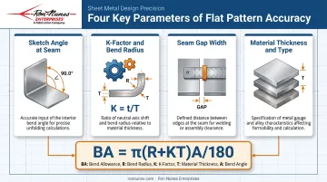
Sketch angle at the seam. An angled cut, rather than a strictly rectangular one, tends to keep the seam edge closer to perpendicular once flattened. A square cut across a curved edge can leave a sliver of acute-angled material that SolidWorks struggles to unroll cleanly.
K-factor and bend radius. These drive the bend allowance calculation. SolidWorks defines K-factor as K = t/T, where t is the distance from the inside face to the neutral bend line and T is material thickness.
Bend allowance follows BA = π(R + KT)A/180. Get K-factor wrong and your flat pattern dimensions won't match the physical rolled part.
Seam gap width. Too tight, and the part won't separate cleanly during cutting. Too wide, and you'll see visible gaps or weld distortion after rolling. This also affects how tightly the part reassembles into its final cylindrical shape.
Material thickness and type. Thicker or harder alloys resist rolling and demand larger minimum bend radii. If your CAD thickness setting doesn't match the actual stock on the shop floor, the flat pattern simply won't reflect reality.
Common Mistakes and Troubleshooting Tips
| Mistake | Fix |
|---|---|
| Rectangular (non-angled) seam cut blocks flattening | Re-sketch the seam at an angle that follows the curve |
| Trying Convert to Sheet Metal on a body with no flat face | Switch to Insert Bends and select a linear edge as the fixed entity |
| Forgetting to unsuppress Flat-Pattern before export | Check the FeatureManager tree—skipping this step exports the 3D shape instead of the flat DXF |
| K-factor mismatched with actual material | Confirm gauge and bend allowance with your fabricator before finalizing the model |
Most of these issues share a root cause: a step got skipped rather than done incorrectly. Building a short checklist into your workflow (seam defined, correct fixed entity chosen, flat pattern unsuppressed) catches the majority of failures before they reach export.
From CAD Model to Finished Part: Manufacturing Considerations
A clean flat pattern in SolidWorks is only half the job. The design still has to survive contact with real tooling, real material, and a real welder.
Before finalizing your model, check these against your fabricator's actual capabilities:
- Minimum bend radius for the material and thickness you've specified
- Hole placement near curved edges, which can distort during rolling or forming
- Seam location, especially if it needs to land somewhere accessible for welding
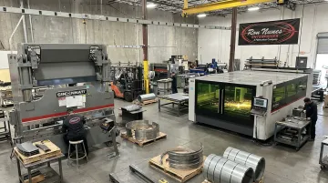
Ron Nunes Enterprises, a full-service fabricator in Livermore, California, has run laser cutting, high-definition plasma cutting, and N/C turret punching since 1969 to blank flat patterns before forming. Their 12-foot Cincinnati 175T Form Master II hydraulic press brake handles angular and complex bending work.
If your part involves a true rolled cylinder or a conical transition, confirm rolling or forming capacity directly with their team before finalizing the seam location in your model.
Share your native SolidWorks file or flat DXF/DWG early. That gives a fabricator time to flag tolerance concerns and confirm the seam weld approach, whether TIG, MIG, or spot welding, depending on material and joint.
It also allows time to line up finishing such as chromate conversion or wet paint before cutting starts. Typical turnaround looks like this:
- Standard stock chassis items: ship within 3 working days
- Custom fabrication: runs about 15 working days
- Curved or rolled geometries: may need a project-specific estimate
Most flattening failures trace back to a skipped seam or angle setup. Fabrication delays, on the other hand, usually stem from bend radius or material assumptions that never got checked with the shop. Catching either one early saves a lot of rework later.
Frequently Asked Questions
Can you convert any cylindrical solid part into a SolidWorks sheet metal part?
Not directly. Convert to Sheet Metal needs a fixed reference face, which pure cylinders often lack. Insert Bends with a defined seam and linear edge reference is usually the more reliable path.
Why won't my cylinder flatten correctly in SolidWorks?
The most frequent cause is a rectangular seam cut that leaves a sliver of acute-angled material at the edge. Re-sketching the seam at an angle that follows the curve typically resolves it.
What is the Insert Bends command used for in sheet metal design?
Insert Bends converts a solid or imported body into a bendable sheet metal part by defining a fixed face or edge. It's especially useful on cylindrical or conical geometry where no flat face exists to anchor the conversion.
How do you cut a slot or hole on a curved sheet metal surface?
Use a straight-through cut-extrude with Normal Cut enabled for simple holes and slots. For more controlled indented or raised detail on the curved face, use the Wrap feature with Deboss or Emboss.
Does the SolidWorks flat pattern account for material stretch when rolling sheet metal?
K-factor and bend allowance settings approximate stretch mathematically, but they're not a substitute for real-world testing. Verify against actual material and thickness with your fabricator before committing to final dimensions.
Who can fabricate rolled or cylindrical sheet metal parts designed in SolidWorks?
Shops with laser cutting, forming, and welding capability under one roof, such as Ron Nunes Enterprises, can take a flattened SolidWorks design from initial cutting through final seam welding to produce the finished part.