The core problem: when those two bends sit close together, standard press brake tooling often can't reach both without the die interfering with the formed flange. Many shops assume that means ordering expensive custom offset tooling. There's a reliable alternative, but it comes with real tradeoffs.
This guide covers when the no-custom-tooling approach works, how to execute it step by step, which parameters matter most, and how to decide when custom tooling is actually the right call.
Key Takeaways
- Offset bends can be formed with standard V-dies using a two-hit method — no custom tooling required when geometry permits
- V-die selection is the critical first decision; die opening must provide adequate clearance for the offset geometry
- Test bends on scrap material are non-negotiable — blank length for offsets cannot be reliably calculated from standard formulas
- Springback varies by material: 304 stainless typically springs back 2–3°, cold-rolled steel only 0.75–1.0°
- Custom offset tooling makes sense when both height and angle require tight control at production volumes
How to Create Sheet Metal Offset Bends Without Custom Tooling
Before setup begins, answer one question: is offset height or offset angle the more critical dimension on this part?
If height is the priority and some angle variation is acceptable, the two-hit standard tooling method is viable. If both height and angle are equally toleranced, stop here and move to custom tooling.
Step 1: Determine the Required Offset Depth
Calculate offset depth by subtracting material thickness from the specified outside offset dimension.
Example: Specified offset 0.156 in. − material thickness 0.059 in. = 0.097 in. offset depth
At this step, confirm with the part drawing whether a strict 90-degree angle is required. If the design specifies true 90° with tight GD&T callouts, the standard two-hit method will not reliably hold that tolerance. If minor angle variation is acceptable, proceed.
Step 2: Select the Right V-Die
Die selection controls whether the offset geometry forms cleanly or binds against the tooling.
The 1.414 multiplier (applied to desired offset height) is a practitioner rule of thumb for minimum die opening, not a published manufacturer standard. Treat it as a starting point, then verify with a test bend.
Available standard V-die openings span a wide range. Common reference points:
| Supplier | V-Die Opening Range |
|---|---|
| Mate American Precision | 0.250, 0.375, 0.500, 0.625, 0.750, 0.875, 1.000, 1.250, 1.500, 2.000, 2.500, 3.000, 4.000 in. |
| WILA Fixed Standard Catalog | 0.157 to 6.299 in. |
Select the nearest available opening that provides sufficient clearance for your geometry. As a thickness cross-check, WILA recommends a V-opening roughly 6–8 times material thickness for steel up to approximately 3 mm.
Step 3: Set the Press Brake Tonnage
Tonnage controls punch penetration depth, which sets the resulting offset height.
The table below shows Mate's published tonnage guidelines for single 90° air bends in mild steel at 60,000 psi tensile strength — these are guidelines, not guarantees, and apply to individual bends, not the combined two-hit offset:
| Gauge / Thickness | V-Opening | Tons/Ft |
|---|---|---|
| 16 ga / 0.060 in. | 0.500 in. | 5.6 |
| 16 ga / 0.060 in. | 0.750 in. | 3.4 |
| 14 ga / 0.075 in. | 0.625 in. | 6.5 |
| 12 ga / 0.105 in. | 1.000 in. | 7.3 |
| 11 ga / 0.120 in. | 0.750 in. | 13.0 |
Material adjustment factors per Mate: Aluminum = 50%, Mild Steel = 100%, Stainless Steel = 150%. Apply these to the mild steel baseline values for your material.
Start with reduced tonnage for the first test bend and adjust from there. Over-forming is harder to correct than under-forming.
Step 4: Manually Stop the Press Brake at the Target Angle
This step separates offset forming from standard V-bending. You stop the ram before full stroke rather than bottoming out.
- Run a test bend on scrap of the same material, gauge, and heat lot before touching any production blanks
- Record the ram stop position that produces the correct offset height on the test piece
- Inspect the test bend for offset height and note actual angle achieved
- Program or mark the stop depth for consistency across the run
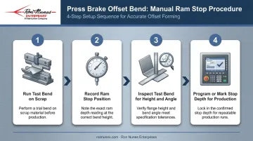
On CNC press brakes with programmable ram stop positions, such as the Cincinnati 175T Form Master II used at Ron Nunes Enterprises, the ram position can be stored in the job program for repeatable results. On manual machines, the operator must consistently stop at the recorded depth, making technique the primary variable.
When Should You Use the Two-Hit Standard Tooling Method?
This approach is not a universal substitute for custom offset tooling. Its suitability depends on the part's functional requirements.
Good candidates:
- Prototypes and first-article parts where tooling cost must be minimized
- Low-to-medium volume runs in chassis, enclosures, brackets, or cover panels
- Parts where offset height controls fit and the angle is not load-bearing
- Early-stage designs that may change before production tooling is justified
Some parts, however, push the method past its reliable limits. Avoid it for:
Poor candidates:
- High-volume production requiring strict part-to-part repeatability
- Parts with GD&T callouts specifying both height and angle simultaneously
- Structural components in defense or telecom assemblies where both dimensions are safety-relevant
- Any design where the center web between the two bends is smaller than 10 times the material thickness, because at that geometry standard two-hit methods break down and dedicated offset tooling becomes necessary
Key Parameters That Affect Your Offset Results
Four variables interact in every offset bend setup — adjust one without accounting for the others and the result shifts in ways that are hard to predict without a test bend.
Die Opening vs. Offset Geometry
Die selection directly shapes your output geometry:
- Undersized die: restricts material flow — expect cracking, distortion, or a tighter radius than designed
- Oversized die: reduces control over final geometry and increases springback variability
- Baseline approach: use the multiplier calculation as a starting estimate, then verify with a test bend
- Ductility factor: higher-ductility materials need less adjustment from baseline; work-hardened or brittle stock needs more
Tonnage and Ram Depth
Too much force over-forms the offset; too little leaves it short. The Mate tonnage values above provide starting ranges for common gauges. For offsets specifically, begin conservatively — you can add force on subsequent test hits, but you cannot un-form an over-bent part.
Material Springback
Springback varies considerably by material. At an inside radius-to-thickness ratio of 1:1:
| Material | Typical Springback |
|---|---|
| 304 Stainless Steel | 2–3 degrees |
| Cold-Rolled Steel | 0.75–1.0 degree |
| Mild aluminum (alloy-dependent) | 1.5–2 degrees |
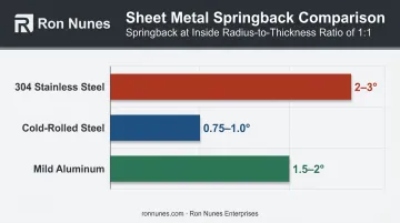
For high-springback materials like stainless or 6061-T6, overbend past the target angle and let the material relax to the desired position. Always verify with the same heat or batch — springback varies between lots.
Ram Stop Consistency
On manual machines, ram stop is the most variable element in the process. Operator technique directly determines whether each part matches the test bend. To hold consistency:
- Record the stop depth immediately after a successful test bend
- Mark the setting clearly on the machine before running production
- Never deviate mid-run — even small adjustments reset your baseline
CNC machines remove this variable almost entirely.
Common Mistakes When Forming Offset Bends Without Custom Tooling
Most problems in offset forming trace back to the same five errors. Catching them before the first stroke saves material, time, and tooling.
- Skip the test bend and you'll run a full batch to the wrong blank length. Standard K-factor formulas don't apply here — the material between two bends can't elongate normally. A test bend is the only reliable way to confirm blank dimensions.
- Wrong die opening cuts angle control at the high end and causes cracking at the low end. Calculate the required opening, reference your die chart, then test before running production.
- Ignoring side thrust damages tooling and distorts parts — especially on longer bend lengths or high-strength materials. Unlike standard V-bending, offset bends push outward in both directions at once. Attach thrust plates to both ends of the tooling.
- Wrong tooling orientation puts the backstop inside the die space. Orient tooling so the workpiece moves downward in front; a backstop collision in a single stroke can ruin both the part and the die.
- Wrong application — if the drawing calls for a precise height and a true 90-degree angle at the same time, the two-hit standard method will produce out-of-tolerance parts consistently. That's an application mismatch, not a setup problem. Custom offset tooling is the correct solution.
Custom Offset Tooling vs. Standard Tooling: Which Is Right for Your Part?
| Factor | Standard Two-Hit Method | Custom Offset Tooling |
|---|---|---|
| Precision | Height controlled; angle varies | Both height and angle controlled |
| Volume | Prototype to medium runs | High-volume production |
| Tooling cost | No additional cost | Investment required |
| Lead time | Immediate | Tooling fabrication time |
| Flexibility | Adjustable per run | Fixed to original design |
| Repeatability | Operator-dependent (manual) or high (CNC) | Consistent across all parts |
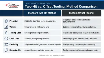
The standard method makes sense for prototypes, early-stage designs, and parts where the function doesn't demand a precise angle. It eliminates tooling cost and lead time while still delivering correct offset height. Fabrication partners with full press brake forming capabilities — including CNC-controlled equipment with programmable stop positions — can execute this method with consistently higher repeatability than shops relying on manual ram stopping.
Custom offset tooling justifies its cost when three conditions align:
- Both height and angle are equally toleranced in the print
- Production volumes are high enough to recover the tooling investment
- Part-to-part consistency is non-negotiable across the run
Industries like defense, telecommunications, and nuclear research — sectors Ron Nunes Enterprises has served since 1969 — frequently meet all three. Tight GD&T callouts and MIL-spec requirements leave no room for angle variation.
Frequently Asked Questions
What is the two-hit standard tooling method for offset bends?
It's a technique for forming offset (Z-bend) profiles using standard press brake tooling in two separate hits, stopping the ram before full stroke to control the offset height. Height accuracy is prioritized; achieving a precise 90-degree angle is secondary.
How do I select the correct V-die opening for an offset bend without custom tooling?
A commonly used starting point multiplies the desired offset height by approximately 1.414 to estimate the minimum die opening needed. Select the nearest available standard die that meets or slightly exceeds that value, then confirm with a test bend. Note that this multiplier is a practitioner guideline, not a published manufacturer specification.
What tolerance can I expect on offset height with standard tooling?
Tolerance depends on machine type, operator consistency, and material. CNC press brakes with programmable ram stops deliver better repeatability than manual machines. Expect some angle variation compared to a true 90-degree offset regardless of equipment.
Can I use this method on stainless steel or aluminum?
Yes, but both require springback compensation. Stainless steel typically springs back 2–3 degrees at a 1:1 inside radius-to-thickness ratio; mild aluminum approximately 1.5–2 degrees. Overbend past the target angle and verify with a test piece from the same material lot before running production.
When is custom offset tooling worth the investment?
Custom tooling makes sense when the part requires both precise height and a strict angle simultaneously, production volumes are high enough to recover tooling cost, and part-to-part repeatability is non-negotiable. If only one dimension is critical, standard tooling usually handles it.
What is the maximum offset height achievable with standard press brake tooling?
It depends on the available V-die sizes and machine tonnage at your shop. Mate's standard catalog tops out at a 4.000 in. V-opening; WILA's fixed dies reach 6.299 in. Larger offsets may require either custom tooling or multiple separate bending operations. The Fabricator confirms that when geometry constraints prevent the standard two-hit approach, dedicated offset tooling is the appropriate path.